


측정방식:
- Diode Laser를 이용한 IR 대역의 in-situ방식
- TDLAS(Tuneable Diode Laser Absorption Spectroscopy)
- NOx, NH3, O2 탈질 설비 제어
- HCI, H₂S 소각로 / 매립지
- O2 정유사 "SAR" 프로세스의 제어
- H₂O CEMS용 모니터링
- O2 폭발 위험 프로세스의 폭발 하한치 제어
- CO, CO₂, O2 정유사 RFCC 프로세스의 모니터링
- CO, O2 보일러, 연소제어, 정유 공장의 히터, 제철공장의 퍼네스 등의 연소제어
- Dust: Scattered/Transmission mode로 근거리(0.5~3m)에서 원거리(~10m)까지 측정

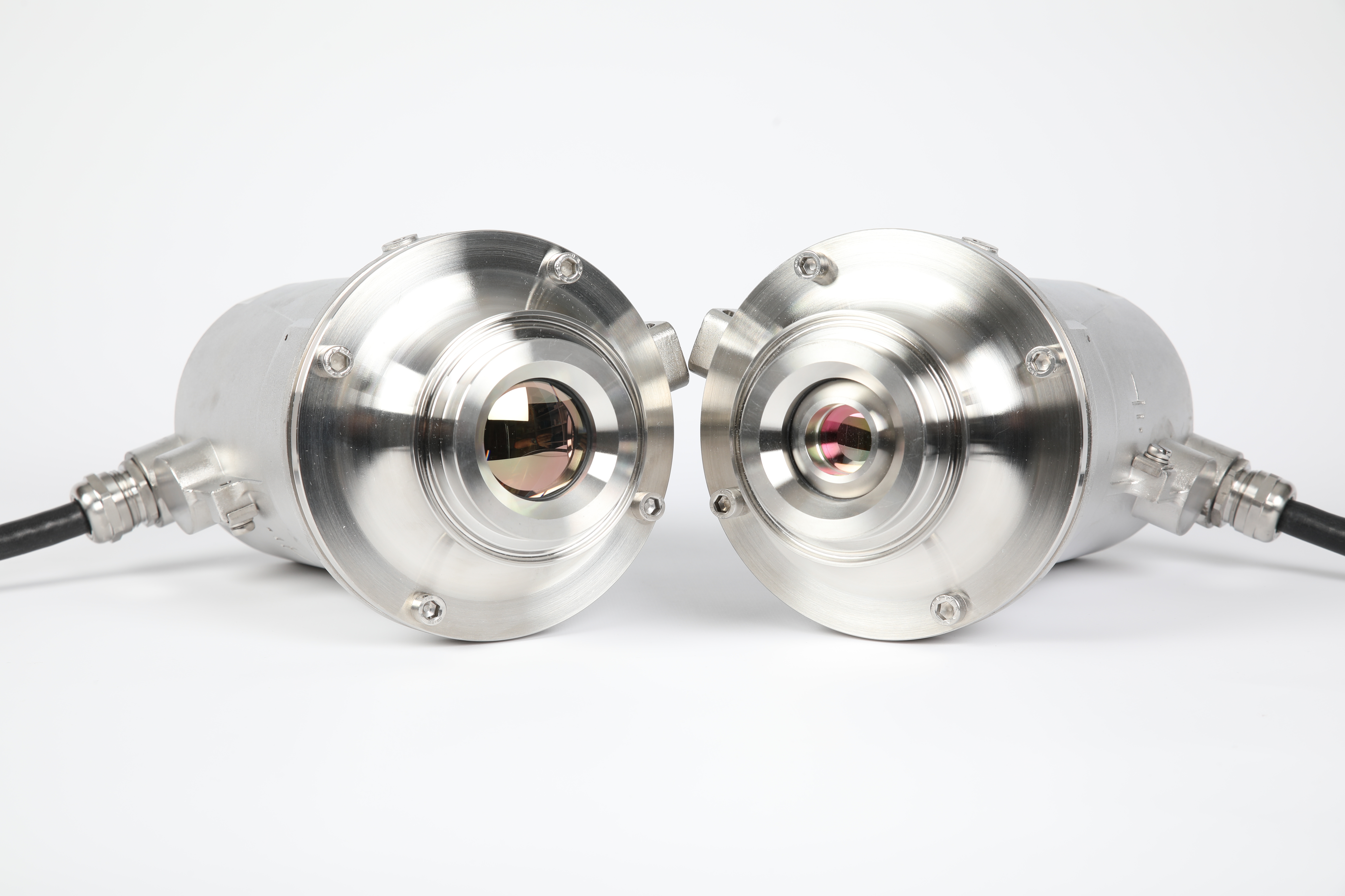
• NEO Monitors의 LaserGas™ III Ultra는 혁신적인 Laser TDLAS 기술을 사용하고 있으며, 연소 분석을 위해 특화 설계되었습니다.
본 모델은 연소 제어 및 안전관리 요구조건을 동시에 충족하고 있습니다. 즉, 높은 측정 정확도와 실시간 측정이 가능하고 폭넓은 측정 범위를 특징으로 합니다. 또한, 긴 측정 경로 및 고농도 가스의 애플리케이션도 문제없이 측정 가능합니다. NEO만의 특허기술인 IROSS 시그널 프로세싱으로 복합 가스 혼합물까지도 측정 정확도가 넓습니다. LaserGas™ III Ultra CO와 LaserGas™ III O2의 조합 설치는 올바른 연소 제어 및 안전관리를 위한 완벽한 구성입니다.
주요 특징
• In-situ 실시간 측정
• Laser TDLAS 기술
• 폭넓은 측정 범위
• 빠른 응답 시간
• 낮은 detection limit
• 주변 가스의 간섭 현상 없음
• 많은 먼지량에도 적용 가능
• 안정적인 Calibration
• Zero drift 없음
• Span check 일체화
• 컴팩트한 디자인
• 10W 이하 낮은 전력 소비
• Ethernet 연결 가능
• CO 프로세스
- 온도 500 미만: 50-100,000ppm*m
- 온도 500 이상: 200-200,000ppm*m
적용 사례
• 연소 제어
• 보일러
• 히터
• 정제 공장
• 발전소
• 화학 산업
• 석유화학 산업
• 제철 및 철강 산업
• 그 외 다수
주요 장점
• 단일 분석기로 프로세스 제어와 안전관리 동시 진행
• 신뢰도 높은 실시간 in-situ CO 측정
• 긴 측정 경로 및 폭넓은 측정 범위
• 적은 연료 소비
• 오염물질 배출 최소화
• 간단한 설치 및 손쉬운 사용법
• 낮은 유지보수 비용
• 소모품 없음
• 샘플링 시스템 불필요
• 압축 에어 퍼지 가능(N2 불필요)
• 연 1회 교정 추천
• 복합 가스
• SPECIFICATIONS
- Detection limit(CO): 0.5ppm**
- Max. process gas temperature: 1300°C
- Detection limit(CO): 0.5ppm**
- Max. process gas temperature: 1300°C
- Max. process gas pressure: 1.5 barA
- Optical path length: Typically 0.5 - 20m
- Optical path length: Typically 0.5 - 20m
- Repeatability: +/-0.5ppm or +/-1% relative, whichever is greater (application dependent)
- Linearity: <1% of range
- Response time: < 5 seconds
- Response time: < 5 seconds
• ENVIRONMENTAL CONDITIONS
- Operating temperatures: -40 °C - +65 °C
- Storage temperatures: -40 °C to +70 °C
- Protection classification: IP65
- Operating temperatures: -40 °C - +65 °C
- Storage temperatures: -40 °C to +70 °C
- Protection classification: IP65
• INPUT / OUTPUT
- Analog output(3): 4 - 20 mA current loop(concentraion CO, transmission, concentration CH4)
- Digital output: 10/100 Base T
- Analog output(3): 4 - 20 mA current loop(concentraion CO, transmission, concentration CH4)
- Digital output: 10/100 Base T
Ethernet (Modbus/TCP)
- Relay output(2): High gas, warning and fault (normally closed)
- Analog input: 4 - 20 mA Process temperature and pressure reading
- Relay output(2): High gas, warning and fault (normally closed)
- Analog input: 4 - 20 mA Process temperature and pressure reading
• RATINGS
- Power supply: 24 VDC, range 18 - 32 VDC
- Power consumptions: max 20W
- 4 - 20 mA output: 500 Ohm max load impedance, not isolated
- Relay output: 1 A at 30 V DC
- Power supply: 24 VDC, range 18 - 32 VDC
- Power consumptions: max 20W
- 4 - 20 mA output: 500 Ohm max load impedance, not isolated
- Relay output: 1 A at 30 V DC
• SAFETY
- Laser class: Class 1M according to IEC 60825-1, eye safe
- CE: Certified
- EMC: Conformant with directive 2014/30/EU
- Laser class: Class 1M according to IEC 60825-1, eye safe
- CE: Certified
- EMC: Conformant with directive 2014/30/EU
• APPROVALS
- ATEX zone 1: Ex db [op is Ga] IIC T4 Gb, Ex tb [op is Da] IIIC T100°C Db
- CSA: Class I, Div.2, Groups B, C and D, T4
- ATEX rating connetion box: II 2 GD Ex e IIC T5, II 2 D Ex e tb IIIC T85°C Db
- ATEX zone 1: Ex db [op is Ga] IIC T4 Gb, Ex tb [op is Da] IIIC T100°C Db
- CSA: Class I, Div.2, Groups B, C and D, T4
- ATEX rating connetion box: II 2 GD Ex e IIC T5, II 2 D Ex e tb IIIC T85°C Db
• INSTALLATION AND OPERATION
- Flange dimension: DN50/PN10 or ANSI 2"/150lbs (other dimensions on request)
- Flange dimension: DN50/PN10 or ANSI 2"/150lbs (other dimensions on request)
- Alitnment tolerances: Flanges parallel within 1.5°
- Purge of windows: Dry and oil-free pressurised air or gas or by fan
- Purge flow: 10-50l/min (application dependent)
- Purge of windows: Dry and oil-free pressurised air or gas or by fan
- Purge flow: 10-50l/min (application dependent)
• MAINTENANCE
- Calibration: Check recommended every 12 months
- Validation: In-situ span check with optional internal cell (application dependent)
- Calibration: Check recommended every 12 months
- Validation: In-situ span check with optional internal cell (application dependent)
• DIMENSIONS / WEIGHT
- Transmitter and receiver unit(TU/RU): 215mm(length, add 50mm for purge unit) x 125mm(diameter), 3.5kg each
- Transmitter and receiver unit(TU/RU): 215mm(length, add 50mm for purge unit) x 125mm(diameter), 3.5kg each
- TU/RU connection box: 260mm x 160mm x 90mm, 2.5kg
♦ Process temperature below 500 °C
| Min | Max | LDL/precision | |
|---|---|---|---|
| CO | 1-50ppm | 0-100,000ppm*m | 0.5ppm** |
| CH4 add-on | 0-1%*m | 0-60%*m | 0.01% |
| Process path length | 0.5m | 30m | |
| Process temperature | -40 ℃ | 500 ℃ | |
| Process pressure | 0.7 BarA | 1.5 BarA |
♦ Process temperature above 500 °C
| Min | Max | LDL/precision | |
|---|---|---|---|
| CO | 1-200ppm | 0-200,000ppm*m | 3ppm |
| CH4 add-on | 0-5%*m | 0-100%*m | 0.05% |
| H2O add-on | - | 0-40% | 2% |
| Temperature add-on | 500℃ | 1300℃ | 30℃ |
| Process path length | 0.5m | 30m | |
| Process temperature | 500℃ | 1300℃ | |
| Process pressure | 0.7BarA | 1.5BarA |
** NOTE: Detection limits are specified as the 95% confidence interval for 1m optical path and gas temperature / pressure = 25℃ / 1barA. Measured in N2.

